Apr 26 2022
Apr 25 2022
Apr 14 2022
Correction to my previous comment: all options are rendered. The only thing is, that the "Vertex" option is hardly visible because it is so small in the 2D views. Since the vertex does not change size with the scale property, I would assume this is by design.
Trying with Windows 10 as well as Ubuntu 20.04, I can only reproduce the option "Vertex" making problems. Everything else seems to work, but this option is not shown in any of the 2D views, only in the 3D view. I used openMeAlone.mps and PointSetForPic3D.mps.
Apr 13 2022
Apr 11 2022
I looked a bit into this. As far as I can tell, there is no such functionality available in the ctkRangeWidget we are using, or the QT classes it is based on. Achieving the proposed behavior would require a large rework. Since the demand for this is very low, it won't be done in the foreseeable future.
Apr 7 2022
Apr 6 2022
I was able to reproduce this on Windows 10, but the behavior seems to be very inconsistent. When testing with Pic3D.nrrd and brain.nrrd, I took the following steps:
- load the image
- create a new segmentation
- draw with the Add- / Region growing - tool in one of the views
- draw again with the same tool in a different view
The behavior then differs depending on which views were used. Generally, when first drawing in the axial view and then in either of the other two, the second addition is not drawn interactively but only shown when letting go of the mouse button. This sometimes also occurs when going coronal -> sagittal or sagittal -> coronal, but never when doing the axial view second.
This only happens when using the same tool in both views without deactivating. If I switch the tool or deactivate and re-activate it, the second drawing works perfectly fine.
I am not able to reproduce this problem on Windows 10 using brain.nrrd as test image
Apr 5 2022
Apr 4 2022
From what I can see, the level window is reset to its original state after pressing "Confirm Segmentation". The darkening / changed level window is only temporary to help adjusting the parameters of the region growing. To me this seems like a feature, not a bug. At least it is by design, anyway.
Apr 1 2022
Mar 31 2022
Mar 30 2022
Mar 18 2022
Mar 15 2022
Mar 14 2022
Mar 7 2022
Mar 3 2022
I tested with MITK v2021.10 and the current state of develop and have the same behavior as @kalali: unconfirmed 3D interpolated surfaces (and contours) are drawn in green. To me this also looks like what is expected from the checklist.
I also get the <segmentation-name>_3D-interpolation node.
I tested with MITK v2021.10 and the current state of develop and also can't reproduce the described problem. In both cases unconfirmed interpolation slices are drawn in yellow.
Amir and I took a look at this in the context of his current work on T28142 (see D601). Because of the unification with the MultiLabel Segmentation plugin, another check is needed for the interpolation area, as interpolation is currently not supported for segmentations with more than one label. So there is the general check, making sure the selected nodes exist and their geometries match up, as well as the check for the correct number of labels (exactly one).
Every time the second check is updated (e.g. when a new label is created) we have to either be certain the first one is currently true, or check the first one again. To avoid adding a new member variable and manipulating/checking it in various places, we decided to just redo all checks together in one place, as this doesn't take too long and is only triggered by user input.
This is captured in D604, which is based on D601 though
Mar 2 2022
Feb 28 2022
Feb 23 2022
Feb 17 2022
Jan 20 2022
Jan 12 2022
Jan 7 2022
This has also been adressed in D568 since the problem turned up there in the CI builds. Should we still solve it in D582 separately or just wait until D568 can be landed?
Dec 23 2021
I think related to this task: it seems there is some more inconsistency depending on the shown region. When two images with different geometries are loaded and shown simultaneously after a global reset, planarfigures created on one of the images can extend into the whole shown region, outside the boundaries of the selected reference image (even after a reset on that specific image).
It seems in this case the boundaries for the planarfigure are set incorrectly on creation.
I can't reproduce the problem mentioned for the mapper plugin on v2021.10 . The moving / target information appears in the properties, just as in a registration created via the Algorithm Control plugin.
Can somebody reproduce this (or a related) problem? Otherwise I guess the task was already solved somewhere else and can be closed
Dec 22 2021
Dec 20 2021
Dec 8 2021
Nov 25 2021
It seems to me like this was done in this commit. Can the task be closed?
Nov 18 2021
Status-wise nothing has really changed since we sent out the messages a while back.
Regarding the last release-cycle: my impression was that it would help to direct testers more to suitable test data. People who have suitable data themselves can still use that, but those who don't are blocked from testing if not provided with data. As I see it, we could either achieve this by either
- naming suitable provided test data explicitly in the checklists
- creating a reference document that lists data types and respective test data
- restructuring / renaming files in MITK-data to make it more clear of what type they are
I think option 2 would be pretty simple to implement and might not reduce the likelihood of people using their own data when possible, as option 1 might do when directly recommending certain test data, but would add another layer of complexity / another file to keep track of (for us, as well as the testers).
Nov 9 2021
Nov 4 2021
Nov 3 2021
I think the problem lies in this difference between the MultiLabel Segmentation Utilities and Segmentation Utilities. For the latter, the "Structuring Element" section looks like this:
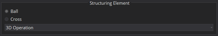
Without the last option, the default seems to be 3D Operation. This causes any Erosion on a single-slice segmentation to delete everything, since it is only one pixel thick. The fix would be to offer the same option in the MultiLabel version of the plugin.
Oct 21 2021
Sep 28 2021
Sep 23 2021
With both subtasks done, we have successfully implemented the main goal of this task. The remaining bug that deactivating a segmentation tool resets the interaction to an earlier state (the one at which the tool was activated) has been split off into T28630 because it is not critical and can be easily handled with the new feature of deactivating PACS tools.
Sep 15 2021
Sep 10 2021
The proposed change goes kind of in the opposite direction of recent changes that were made, specifically in D531 and part of D532. If the approach of D535 is to be continued, it would need to take into account D532, in which an additional PACS scheme was introduced that leaves the left mouse button unused.
I would personally prefer the direction we have been taking now, splitting up the config files into smaller chunks. This reduces code redundancy, instead of having almost identical config files many times.
Also, in my opinion the approach of D531 makes a lot of sense for overlapping interactions. It allows to change only the aspects of interaction that are necessary while staying oblivious to the current interaction (MITK default, with swivel, PACS, ...). If we want to use full configs, one would need any variation of each scheme for each situation where alterations may be necessary. For example 2D segmentation tools require the left mouse button, so any possible interaction scheme needs to have a corresponding version where the left mouse button is unused. If a tool requires something new, like the right mouse button, new config files have to be implemented for every existing interaction scheme instead of just one file that will be appended.
Aug 25 2021
Possible duplicate of T28278? That task's description is not very clear about the problem, but could be referencing the same thing