Page MenuHomePhabricator

Render windows show *not* the corresponding orientation after reinit with permuted axes
Closed, ResolvedPublic

Assigned To
Authored By
espak
Dec 6 2016, 1:53 PM
Referenced Files
F763212: image.nrrd
May 12 2017, 11:35 AM
F56327: happycat.jpeg
Jan 12 2017, 7:57 PM
F56034: 800px-DICOM-OrientationDiagram-LPS.png
Jan 12 2017, 2:23 PM
F54537: aVDrmPO_460sv.mp4
Jan 10 2017, 12:59 PM
F41046: MITK-Geometries (3).png
Dec 20 2016, 2:10 PM
F41039: MITK-Geometries (2).png
Dec 20 2016, 1:45 PM
F40623: screenshot.jpg
Dec 19 2016, 12:51 PM
F38383: Screen Shot 2016-12-15 at 11.02.55.png
Dec 15 2016, 12:06 PM
Tokens
"Party Time" token, awarded by kislinsk.

Description

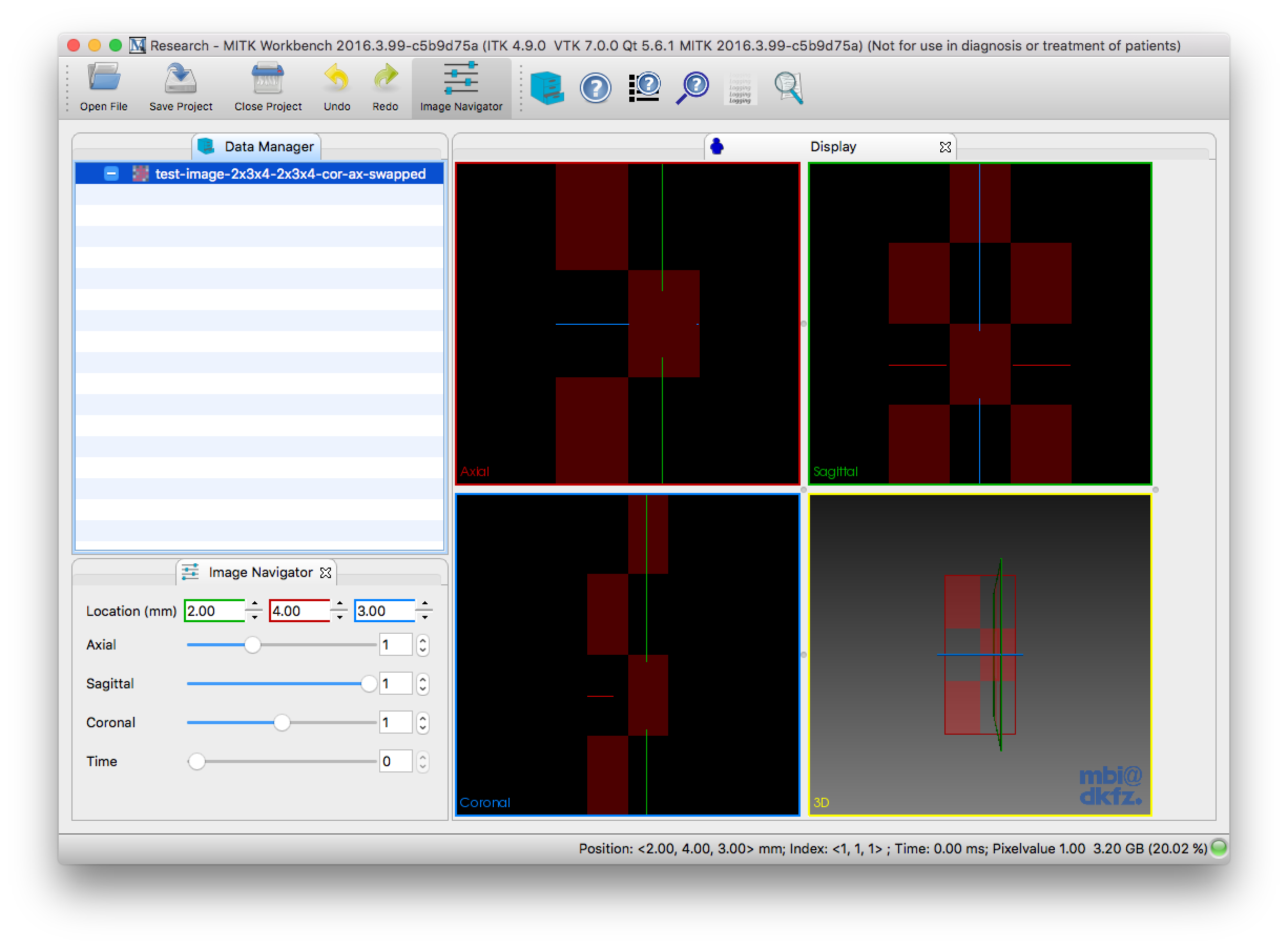
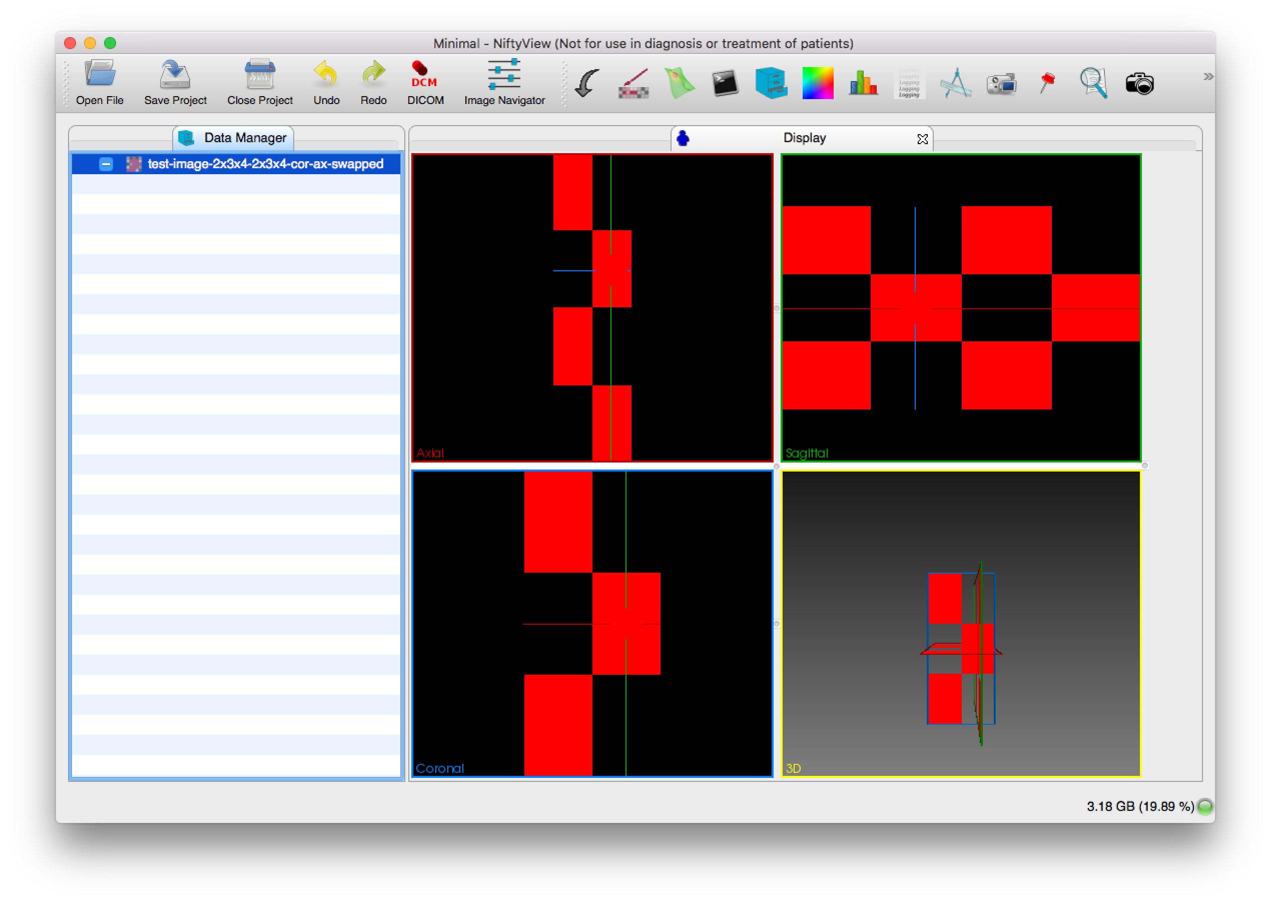
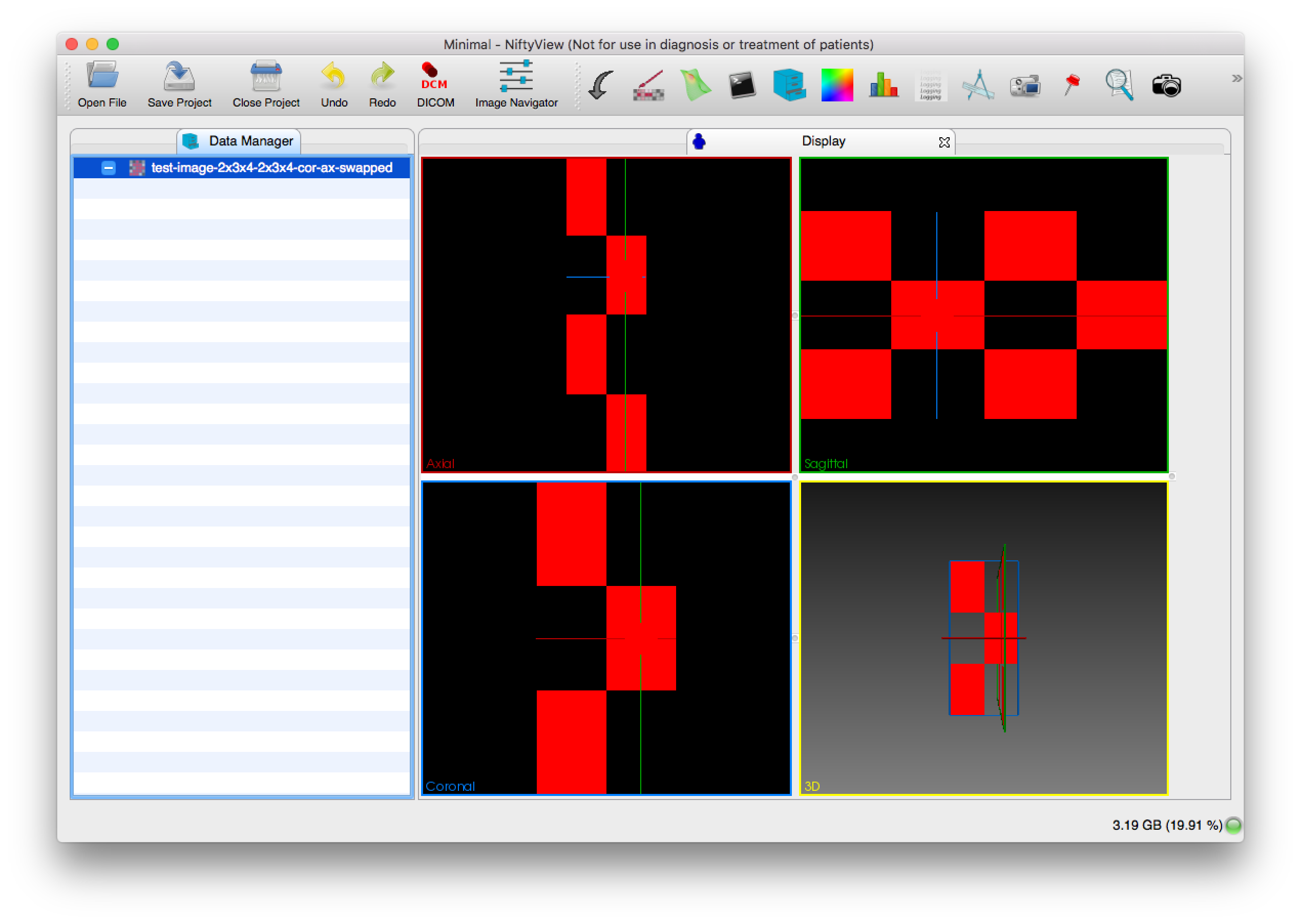
See the screenshots with an image in which the coronal and axial axes are swapped and both are flipped.

cor-ax-flipped-global-reinit.png (1×1 px, 318 KB)

cor-ax-flipped-local-reinit.png (1×1 px, 324 KB)

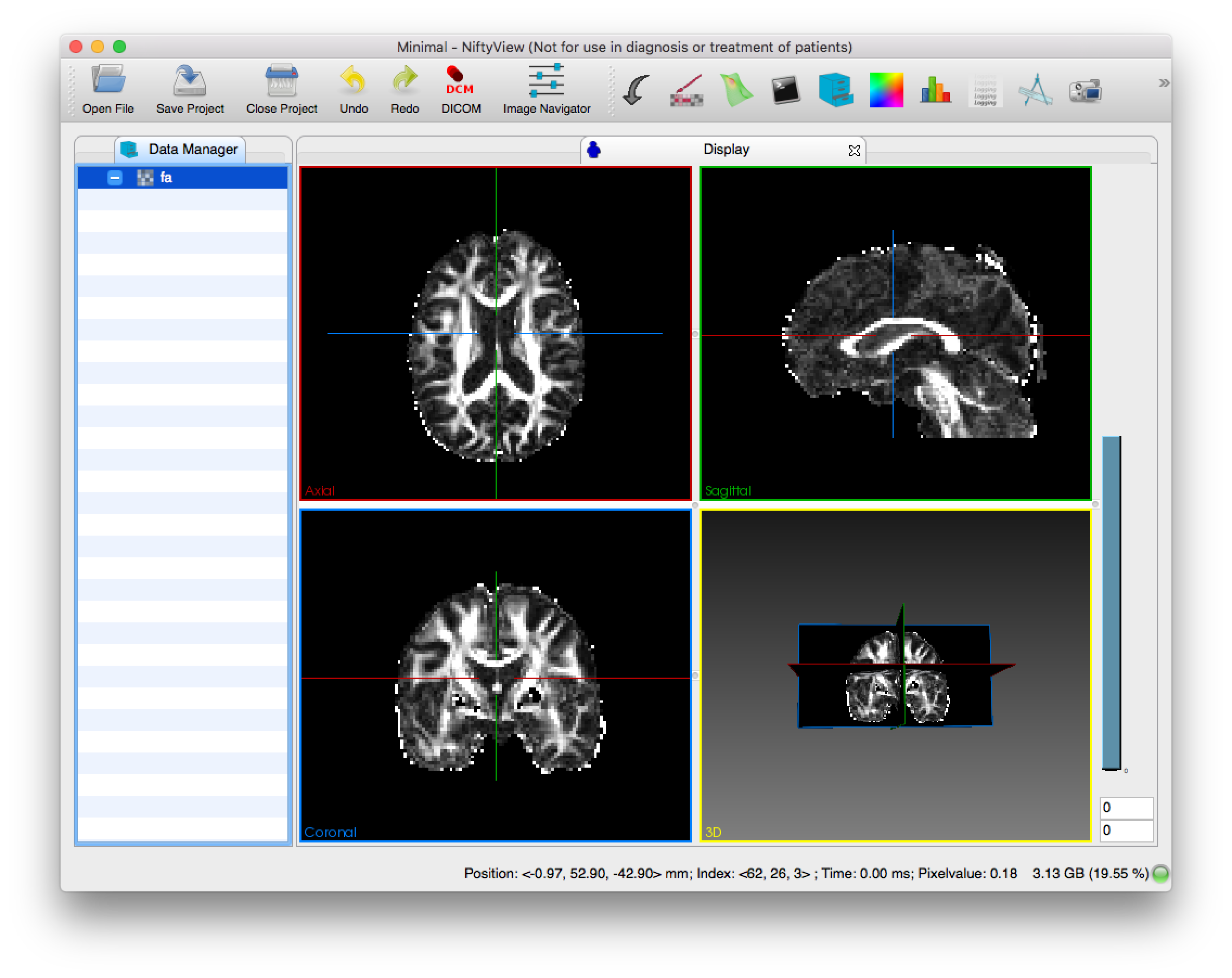
After reinit the coronal window shows the axial view and the axial window shows the coronal view and the axes are swapped in the sagital window, so the image looks as if it was mirrored on a diagonal.

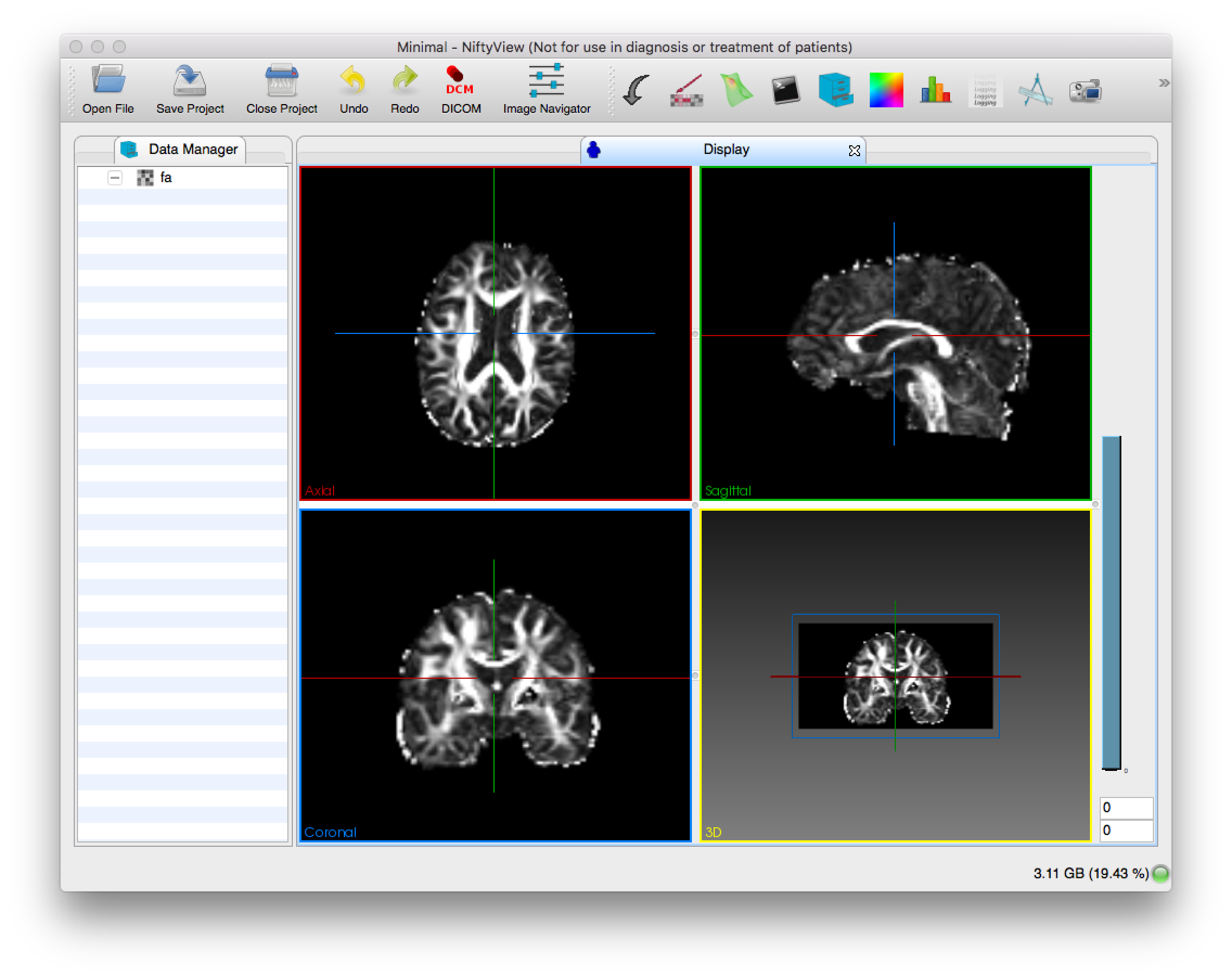
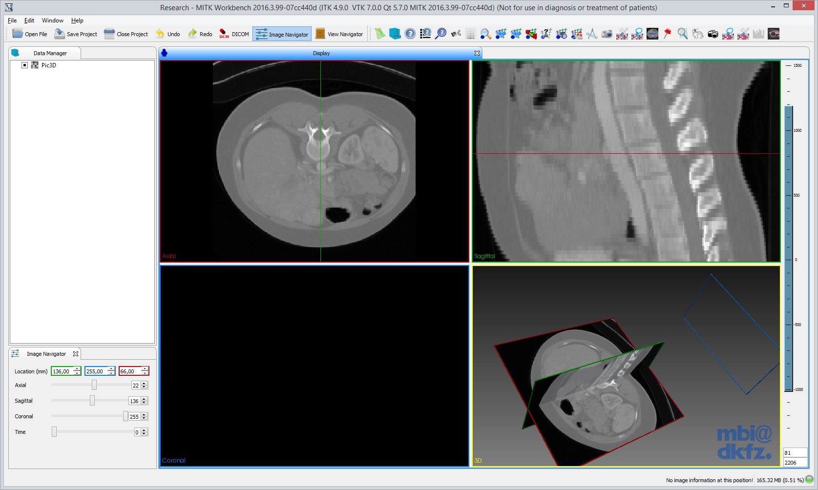
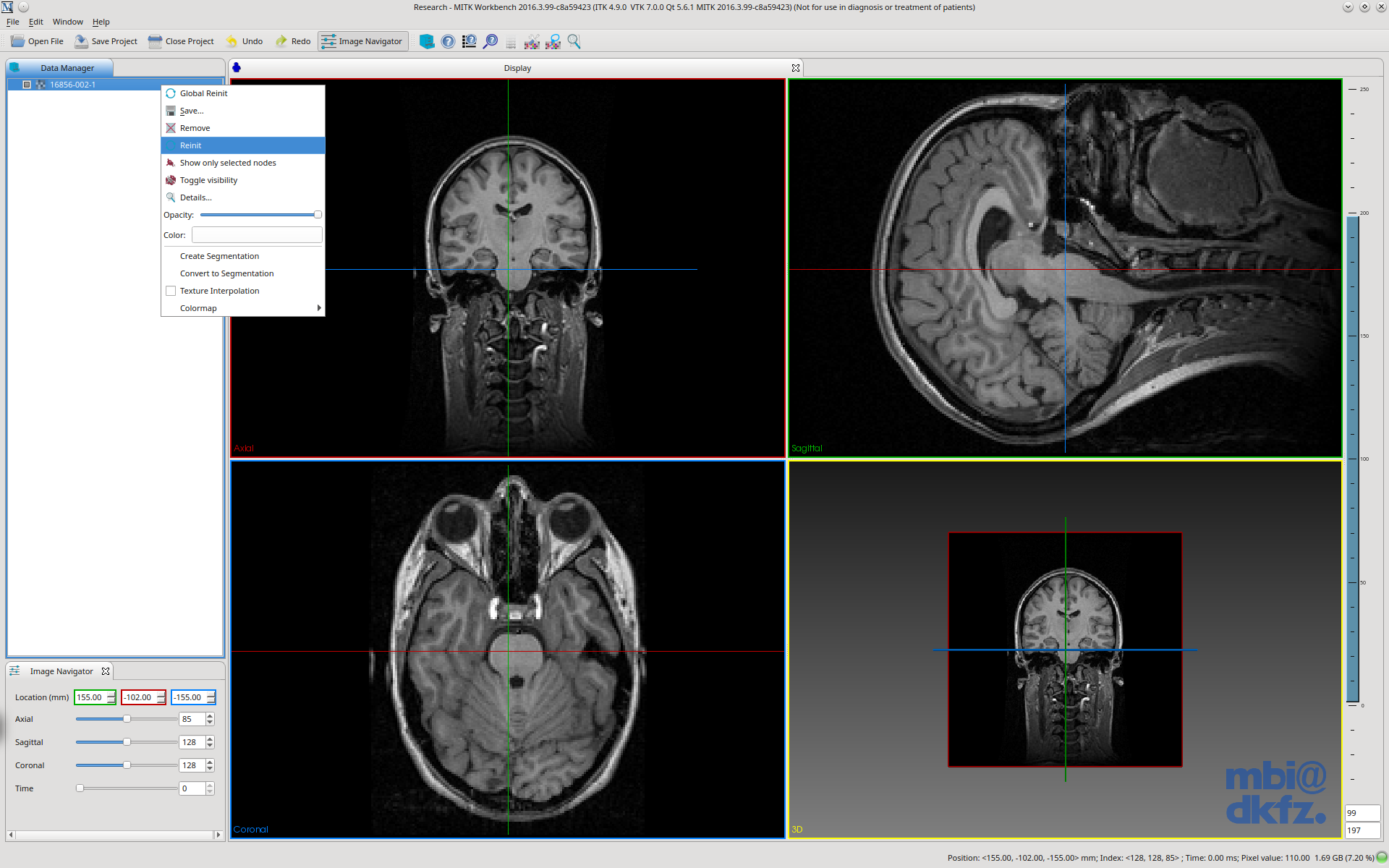
However, I would expect the coronal window to show the image in coronal orientation, the axial in axial orientation and the sagittal in sagittal orientation, and the patient's right should be on the left side of the axial and coronal windows and the patient's nose should be on the left side of the sagittal window, according to radiological convention that MITK follows.

So, basically, you should see the same as after global re-init if this is the only image in the data manager.

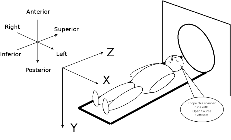
In case you find this invalid and you want to display the images in voxel space with the original orientations, then the annotations should be corrected in the render windows and there should be new annotations on each side of each window that show the directions 'L', 'R', 'A', 'P', 'S' and 'I'.

I have a simple vtk class to display the direction annotations that I would be happy to share with you guys.

Note that this is slightly related to T22114, although the original statement of T22114 was wrong. The images with flipped axes do show up in the renderers now, just in (IMO) wrong orientation. The check-pattern images are obviously not ideal to point this out. :-)

Here is the image that I used to make the screenshot.

PR160 that I did for T22114 fixes this issue.

Related Objects

Mentioned In
T25682: mitkBaseGeometry.cpp: Internal ITK matrix inversion error, cannot proceed.
T22839: Label Noise in the Clipping Plane Plugin.
T20180: Axial renderer origin in top-left-front corner, not in the bottom-left-back
rMITK0d5dc7bff161: Merge branch 'T22254-Fixes'
rMD826b368fc043: Revert rendering test data (T22254).
rMITKa1730ffab6ec: Merge branch 'T22254-Fixes'
rMD8b1f9bd86c42: Adapt reference data to T22254.
rMITKbbe4c8ca8f81: Merge branch 'T22254-Fixes'
rMD714a1d6441ca: Adapt reference data to T22254.
rMITK297be0946973: Merge branch 'T22254-Fixes'
rMITK73bae61b0eae: Merge branch 'T22254-Fixes'
rMITK5798d2546e52: Merge branch 'T22254-GeometryFixesBasedOnReleaseBranch' into releases/2016-11…
rMITK68e3fc8eb166: Merge branch 'T22254-GeometryFixesAsProposed'
rMITK3ffe1606e87c: Merge remote-tracking branch 'NifTK/T22254-all-geometry-fixes' into T22254…
rMITK07cc440db371: Merge remote-tracking branch 'NifTK/T22254-all-geometry-fixes' into T22254…
T22114: re-init does not work with images with flipped axes
Mentioned Here
T17812: SlicedGeometry3D initialisation fix for non-image geometries
rMITK8fcd82ec6327: Correct handedness of coronal renderer geometries
rMITK7cbcdad3e42c: SlicedGeometry3D::GetReferenceGeometry() function for API consistency
rMITKc9dbcfcd4360: Current world position re-calculated before updating status bar
rMITKf34cc3982951: Correcting origin and bounds for geometry calculated from data storage
rMITKa773ec628622: Turn spacing vector to world coordinate order for bounding box geometry…
rMITK946ee54121a7: Equality checks when setting data storage for renderers
T20218: DataStorage::ComputeBoundingBox3D creates geometry with incorrect origin and bounding box
rMITKc5b9d75a7660: Merge branch 'T20070-fix-cpu-volume-rendering-crash'
T20180: Axial renderer origin in top-left-front corner, not in the bottom-left-back
T22113: Image navigator should show image indices after re-init
T22114: re-init does not work with images with flipped axes

Event Timeline

There are a very large number of changes, so older changes are hidden. Show Older Changes

I wanted to compile and test it myself but I stopped trying when I read kislinsk reply., so here's my image

.
I don't know if this patch is trying to fix the same problem I have; I have no big rotation problem like in the image above, I just want Reinit to keep the minus signs in the affine, so the user is not too confused when segmenting an image.

So, yes, thank you for your kind offer to send a screenshot :)

Sorry, this was after global re-init, as you can see it in the sagittal window.
Here is the screenshot after re-init, with texture interpolation off.

Screen Shot 2016-12-09 at 08.54.51.png (1×2 px, 253 KB)

Ah, nice! Yes, this is exactly what I had in mind. Stuff staying mostly where it was but now aligned on the grid. Thank you.

@kislinsk

Note that if this gets accepted, it will probably validate T22113, that means after PR160 (or similar) you will need PR161 (or similar) to see correct indices in the image navigator.

After I re-tested T22113, it seemed to be fixed on the master, but I was probably using the check-pattern test images. The indices were correct and consistent with the status bar, but the orientations must have been mixed up in the render windows, just I did not notice it with the check-pattern.

And you *might* need the five commits from T20180, but not sure. These issues are all related, that's why it is difficult to discuss them under individual tickets.

I totally agree that all these issues are quite difficult to discuss in individual tickets and I would prefer to close all of these tasks in favor of a single one (this one?). I'd then like to create a branch based on our release commit rMITKc5b9d75 to gather all relevant commits for the fix. Therefore I'd like to ask you to check/fix your pull requests as at least PR160 doesn't work at the moment. As soon as you give it a go, I would then cherry pick all relevant commits into the branch.

kislinsk triaged this task as High priority.
kislinsk edited projects, added MITK (2016-11); removed MITK.
kislinsk moved this task from Backlog to Focus Tasks on the MITK (2016-11) board.

What should be the target branch of the updated PR?

I guess, it should be "releases/2016-11-beta" but that is not pushed to github, so I create the PR against master.

I am not sure what is the 'None' plane orientation supposed to mean. I added 'None' as the same as the 'Axial' case, as I saw at another place in the same file, here:

https://phabricator.mitk.org/source/mitk/browse/master/Modules/Core/src/DataManagement/mitkPlaneGeometry.cpp;70a8f303d39d833fc65d1e549c3b7931fcb4b576$228

This should resolve the crash.

I created PR172 that is the same as PR160 plus the two "case None:" lines, and rebased on the commit you told.

Great, thank you! As long as it is based on rMITKc5b9d75, it is prepared for being included in releases/2016-11-beta, as at this point the branch was branched off. Does PR172 contain everything that's needed for all the Reinit issues?

I updated PR172 with two commits from PR161.

So, it has now:

  • 5861f34 Translate input geometry to world space for calculating sliced geometry planes

That fixes the orientations after re-init.

  • 4cddd65 Invert directions in image navigator according to reference geometry

That corrects the indices in the image navigator. (The previous commit messes them up.)

  • b71ca9e Invert slider control directions in image navigator

Inverts the slider controls so that they work 'as in world space'. You told you don't want that, but after you will see the issue, you might change your mind. :-) I found it more confusing not to turn it than to turn it.

I tried to cherry-pick the commits for T20180 on the top, but as I see, part of the issue has been fixed in the master already, e.g. mitk::PlaneGeometry::EnsurePerpendicularNormal() should preserve the handedness now according to the comments. I will try to apply the rest.

Thank you, please let us know, when the PR is final and ready for testing. I doubt that we'll change our mind on the inverted sliders, though. ;-)

I tried the first commit of PR172 that is supposed to resolve this, but on top of rMITKc5b9d75 it makes the render windows blank.

However, I discovered another problem that happens with rMITKc5b9d75 after global reinit that I believed we had resolved already.

Input image:

MitkWorkbench, global re-init:

Screen Shot 2016-12-15 at 11.00.36.png (1×2 px, 226 KB)

MitkWorkbench, re-init:

Screen Shot 2016-12-15 at 11.02.04.png (1×2 px, 226 KB)

NiftyView, global re-init:

Screen Shot 2016-12-15 at 11.02.55.png (1×2 px, 193 KB)

NiftyView, re-init:

Screen Shot 2016-12-15 at 11.03.33.png (1×2 px, 192 KB)

Could you give another commit where the previous geometry fixes are already applied? Especially T20218.

Could you push the release prepare branch to github, eventually so that I could make a pull request against that? Or does phabricator allow something similar?

Hm, I think the easiest way of getting the previous fixes is by either cherry-pick the fixes into your PR branch, or by rebase it on the master. As the Geometry fixes won't end up in 1000 commits, it shouldn't be too hard to cherry-pick them back to the release branch.

Your commits in the release branch currently are:

rMITK7cbcdad3e42c: SlicedGeometry3D::GetReferenceGeometry() function for API consistency
rMITKc9dbcfcd4360: Current world position re-calculated before updating status bar
rMITKf34cc3982951: Correcting origin and bounds for geometry calculated from data storage
rMITKa773ec628622: Turn spacing vector to world coordinate order for bounding box geometry…
rMITK946ee54121a7: Equality checks when setting data storage for renderers

For easy copying:

7cbcdad3e42c
c9dbcfcd4360
f34cc3982951
a773ec628622
946ee54121a7

PR160 was based on master, originally.

The second commit is invalid. I get this error:

error: malformed object name c9dbcfcd4360

I fetched http://git.mitk.org/MITK.git and git@github.com:MITK/MITK

I go back to master but I need to rebuild everything as the minimum CMake version has increased.

So, PR172 should now contain all the proposed changes.

Little glitch with 113870c (Invert directions in image navigator...):

The image navigator checks if the directions are inverted when you interact with the render window or with the image navigator GUI controls. But it does not listen to the geometry changes of the renderers. So, right after that the renderers get a new geometry (e.g. re-init or global re-init), the displayed indices might be incorrect, but they will be corrected after any interaction, e.g. clicking into any render window or changing any spin box or slider of the image navigator.

And another glitch that is even more minor.

The image is not at the same position in the 3D window after re-init and global re-init. It looks to be in the middle after re-init, but it is placed a bit lower after global re-init. It is still inside the 3D window, and it is orientated in the same way.

My guess is that the origin is slightly off for the geometry of the 3D renderer. It is created in mitk::DataStorage::ComputeBoundingGeometry3D().

I noticed it with the 2x3x4 check-pattern images that are attached to T22114.

The changes unfortunately seem to break like "everything". The Coronal plane is completly off and touches the actual image volume in only one slice. The other windows are mirrored and/or upside down. This is our Pic3D.nrrd (same problem with every other image I tried, though):

screenshot.jpg (1×1 px, 293 KB)

Sorry, silly mistake. :-(

As I told, I needed to make a little API change. I had to pass down the 'top' property to a few more PlaneGeometry functions. The 'top', 'frontside' and 'rotated' parameters are usually listed in this order, and that's how I implemented this change on our fork, but in the PR I put the new 'top' parameter to the end of the argument list, so that I do not accidentally break the current function calls.

I mean that was the intention, but I forgot to permute the parameters for one of the functions.

Here the arguments should be 'frontside', 'rotated' and 'top' so that the new parameter is at the end:
https://phabricator.mitk.org/source/mitk/browse/T22254-GeometryFixesAsProposed/Modules/Core/src/DataManagement/mitkPlaneGeometry.cpp;07cc440db371a5906b937ea4dd7cc21d1ad99dc4$385

I updated the PR.

I also rephrased some commits.

A bit of an explanation about the last commit:

8fcd82ec6327 "Correct handedness of coronal renderer geometries"

MITK-Geometries (3).png (452×795 px, 60 KB)

Currently the origin of the geometry of the coronal renderer is at C and the coordinate system is left-handed. The commit changes the coronal origin to C' so that you can have a right-handed coordinate system for the coronal renderer as well.

As you can see in the figure, the right vector (x) and the bottom vector (y) is the same that means you will see the slices in same way on the screen. However, the normal is inverted that results in changing the order of the slices. Scrolling through slices will go in the other way than till now.

Note that the origin is in the bottom-left-back corner of the observer's view in case of the sagittal and axial views, but not for the coronal view, currently.

This commit is not necessary for solving the issue with the permuted axes, so you guys need to decide if you agree with the change or not.

Thank you for the explanation, Miklos. I'll give it another try tomorrow, as I'm currently in the middle of another complicated bug. :-/

Had to fix a a wrong signature as the top parameter was present twice, but now it looks very promising in the first tests.

That's totally possible. The PlaneGeometry API was already a bit messy, and my commit made it worse by adding 'top' at the end. (Some functions had 'top' somewhere at the beginning already, not directly before the 'frontside' and 'rotated' args as usual.)

One day it would be worth tidying it up a bit.

But functionally speaking, it is quite flexible. The only cases that are not supported are when the x and y axes are swapped. That means you cannot view the subjects from the side (rotated by 90/270 degrees). That could be allowed by adding a new flag. I am not sure, though, if there is a valid use case for that. We certainly do not have.

Just for the record, a few suggestions if you guys want to clean up / redesign the PlaneGeometry API at some point:

Not strictly necessary, but instead of top, frontside and rotated, I would probably use flipX, flipY and flipZ to control the axis directions independently. The meaning of the current flags are: top == !flipZ, frontside == !flipX, rotated == flipX && flipY. So, now if you want to flip only the 'y' axis, you have to set unset frontside and set rotated.

There could be a new arg called swapXY to swap the x and y axes to support all the missing cases.

And I would eliminate zPosition from the API, and would pass down a depth argument, instead, (just like width and height is used now) and a slice index (except in InitializeStandardPlane where it is 0).

The long function with the 12 if-else cases could be written in a much more concise way without that long if. Now it's OK but with a swapXY arg there would be 24 cases.

But this could be a scope of a new task if there is an interest.

Fixed remaining compile errors in tests. We need to adapt the following two tests:

  • mitkPlaneGeometryTest
  • mitkSlicedGeometry3DTest

Just to let you know, I started working on the two tests above again after the holidays. The SlicedGeometry3DTest is done, the PlaneGeometryTest follows.

@espak The asserts in the PlaneGeometryTests that fail are always because of the normal pointing in the opposite direction as expected by the test. In one example the frontside parameter when initializing the plane geometry is set to false and then its normal is checked against (-normal). Is it expected that the normals after your changes in these cases are flipped?

Which asserts?
Line 468 and 496 here?
https://phabricator.mitk.org/source/mitk/browse/T22254-GeometryFixesAsProposed/Modules/Core/test/mitkPlaneGeometryTest.cpp;4261ef7a44c7e44b4a7b38a9781533235a366293

The plane normal should point in the same direction as the z (2) axis vector of the plane geometry (or the sliced geometry).

The direction can be either way, as you can create left or right handed systems as well. If right handed, the direction is the same as the cross product of the righ and bottomvectors. If left-handed then the normal points in the opposite direction. You can create left-handed plande geometries by specifying negative thickness.

Sorry, forgot to add the line numbers:

  • 749
  • 801
  • 836
  • 872

My guess is that the minus sign has to be removed from line 750 and 773.

The frontside flag does not affect the z axis (normal). Frontside flips the x axis, top flips the z xis and rotated flips x and y.

Thank you, everything was successfully merged into the master branch and the release branch. I guess there are some PRs that need to be closed manually now?

Some other tests fail after the geometry changes on our dart clients. So it's not over yet. :)

These tests fail, as I see:
http://cdash.mitk.org/viewTest.php?onlyfailed&buildid=643361

What regards the pointset data interactor and the surface mapper tests, I think the test reference data has to be regenerated. I had to do this this for T17812, you can find that test data under the task. But that was a different issue (half voxel shift of renderer geometries), so I do not assume that the test data from there will work here 'as is'.

For ImageTest, could you try to add this line:

planegeometry->SetImageGeometry(true);

after this:

https://phabricator.mitk.org/source/mitk/browse/releases%252F2016-11-beta/Modules/Core/test/mitkImageTest.cpp;5798d2546e5246c68c0aa24f90da3473a026a133$283

This might resolve the warning, but I do not know if this make the tests fail, actually.

For the image test, the missing image geometry flag wasn't the actual problem. The problem is that mitk::Image::Initialize() has a parameter called flipped. As you changed a similar signature in the InitializeByStandardPlane() methods of a geometry, this bool flag was now passed as number of slices (false -> 0). I fixed it by making the Initialize() method deprecated and adding a new signature without the flag.

I have trouble with the mitkSliceNavigationControllerTest, though. The frontal case fails and I didn't get it. It doesn't seem to be a changed sign problem alone. Would be really cool, if you could have a look at the test. It can be executed by the CoreTestDriver.

The PointSetInteraction test seems to be tricky as well as a few points out of many have a difference of 1 in the second coordinate (128.x vs 127.x).

I will rewrite the SliceNavigationControllerTest, as it is highly confusing. For the new test, I will assume the following points:

  • MITK uses OpenGL which has a right-handed coordinate system with x pointing to the right, y up, and z out of the screen
  • The three axis vectors of the geometry express the LPS extents in this frame
  • The axial view looks from the feet to the head, while the back of the patient is at the bottom of the screen, implicating that the left side of the patient is on the right side of the screen
  • The frontal/coronal view looks from the front to the back of the patient, while the feet are at the bottom of the screen and the left side of the patient is on the right side of the screen
  • The sagittal view looks towards the right (!) side of the patient, while the feet are at the bottom of the screen and the back of the patient is on the right side of the screen, the scrolling direction is as expected towards the left, though

800px-DICOM-OrientationDiagram-LPS.png (487×800 px, 78 KB)
https://www.vtk.org

Example

Assuming a frame specified in LPS with 100 50 200 at origin 10 20 30 with a z-spacing of 2 should result in the following slice navigation controller geometries:

Axial

Origin1020+50=7030+200-1=229
Axis Vector 010000
Axis Vector 10-500
Axis Vector 200-200

Coronal

Origin1020+50-0.5=69.530
Axis Vector 010000
Axis Vector 100200
Axis Vector 20-500

Sagittal

Origin10+0.5=10.52030
Axis Vector 00500
Axis Vector 100200
Axis Vector 210000

The assumptions are valid at the top.

Yes, the sliced geometries have a half voxel shift along the normal relative to the corner point. But the corner point is not necessarily in the origin. Only for non-image geometries.

So in your example:

100 50 200 are the extents in mm
10 20 30 is the origin in mm
slice thickness is 2mm

Is (10,20,30) the origin of an image geometry? Are you creating a non-image sliced geometry?

Are these isotropic voxels? I mean the slice thickness is 2mm in all the directions?

This would result in 50, 25 and 100 slices, respectively, in your example.

Or you mean three different cases, in each case the voxel with and height is 1mm and the thickness is 2mm?

Why would the z axis vector be shorter than the depth of the volume? The axis vector should be equal to the normal times the number of slices, shouldn't it?

So, to calculate the expected values, first we have to find the corner point with the lowest physical coordinates. It's the origin of the x, y and z vectors on the figure above.

In this figure I denoted it as W:

https://phabricator.mitk.org/file/data/rtr74k3uja3jbgg4talb/PHID-FILE-5itfrpyy5i67f7bukuqh/MITK-Geometries_%283%29.png

Then we can find the "sagittal", "coronal" and "axial" origin, relative to W. (It agrees with the assumptions in your post.)

Then you have to shift the result with half normal for the reason you told.

https://phabricator.mitk.org/file/data/rtr74k3uja3jbgg4talb/PHID-FILE-5itfrpyy5i67f7bukuqh/MITK-Geometries_%283%29.png

We also have to permute the indices. E.g. in sagittal x points downwards that means the length of the bottom vector (aka. height) will match the length of the y vector in the "anatomic" coordinate system. (In the top in the figure.)

Basically, you have to match the individual axes to each other.

Does it make any sense?

happycat.jpeg (740×600 px, 190 KB)

It is a non-image geometry. Voxel width and height are 1mm each, thickness 2mm. The "Actual" tables show the values of the origin/axis vectors with the current master implementation (including your fixes).

I'm confused about the sagittal case in particular. When the back of the patient is on the right-hand side of the screen, and the feet are at the bottom... shouldn't we look towards the right side of the patient instead of the left side as it is currently? How can we look towards the left side without mirroring something (as the back is on the right and feet are at the bottom)? In this view I would expect to scroll through the heart first and not at the end of the range.

In sagittal we see the left side of the face of the patient, i.e. we are looking towards the patient's right, what is on their other side. We can't see their right.

The actual values all look correct to me.

Volume size: 100 50 200

That means:

  • sagittal dimension (left-right) is 100mm
  • coronal/frontal dimension (posterior-anterior) is 50mm
  • axial dimension (inferior-superior): 200mm

Spacings are:

  • sagittal: 1mm
  • coronal/frontal: 1mm
  • axial: 2mm

Hence, the extents in number of voxels:

  • sagittal: 100vx
  • coronal/frontal: 50vx
  • axial: 100vx

Origin coordinates:

  • sagittal: 10mm
  • coronal/frontal: 20mm
  • axial: 30mm

The renderers must get a geometry where the axes are permuted. In each renderer the first (x) axis is the horizontal axis, the second (y) is the vertical axis and the third (z) is perpendicular to the renderer plane. We can also say that "width" is the length (magnitude) of axis vector 0 (x), "height" is that of axis vector 1 (y) and "depth" is that of axis vector 2 (z).

This is true in each renderer, just it changes which axis (x, y, z) which anatomical directions (sagittal, coronal, axial) correspond to.

For instance, in the sagittal renderer you want to see:

  • x axis: coronal/frontal
  • y axis: axial
  • z axis: sagittal

Accordingly:

  • width: coronal dimension (50mm == 50vx)
  • height: axial dimension (200mm = 100vx)
  • depth: sagittal dimension (100mm == 100vx)

In terms of axis vectors, not considering the direction yet, you get:

  • axis vector 0: (0, 50, 0)
  • axis vector 1: (0, 0, 200)
  • axis vector 2: (100, 0, 0)

These would be the final axis vectors if the "sagittal origin" was at the same place as the "world origin". And in this case it actually is, so we are done.

In the coronal renderer you want to see:

  • x axis: sagittal
  • y axis: axial
  • z axis: coronal

Accordingly:

  • width: sagittal dimension (100mm)
  • height: axial dimension (200mm)
  • depth: coronal dimension (50mm)

In terms of axis vectors, not considering directions yet, you get:

  • axis vector 0: (100, 0, 0)
  • axis vector 1: (0, 0, 200)
  • axis vector 2: (0, 50, 0)

The magnitudes of these vector give the expected length, but this is not everything. There are 7 other sets of vectors for which the same is true. (You can negate any of the axis vectors.) The origin and the direction of these vectors determine from which side you are seeing the patient. The set of vectors above is valid, but it will show the patient with eyes facing down and from the skull, not from the feet. If you want to get the correct orientation, you have to move the origin "on the other end" and you have to flip the axis vectors accordingly.

Note that if you change one coordinate of the origin, you have to flip the corresponding axis vector, otherwise you will describe a different volume.

Does this make sense so far?

This is very odd as it doesn't fit nicely into the LPS scheme, where we're moving along the positive axes in the P and S case. So at the moment we are looking from the patient's left to the right but we're scrolling from the patient's right to the left. Can you confirm?

edit: mid-air collision with your long comment. :-)

No, scrolling up should go to the slice behind in any render window. In sagittal, scrolling up should go towards the patient's right. It was like this when I was testing. If it is not like that, something is wrong.

Referring to your long comment: Yes, this makes sense and it is what I tried to do. I had a wrong assumption, though, regarding the view direction for the L-axis, in which case, for whatever reason, we have look along the negative axis. In the P-case we look from anterior towards posterior and in the S-case we look from inferior towards superior.

In T22254#91916, @espak wrote:

No, scrolling up should go to the slice behind in any render window. In sagittal, scrolling up should go towards the patient's right. It was like this when I was testing. If it is not like that, something is wrong.

We need to sync our comments again. :-) I tested also on old releases and it's always looking towards the patient's right, but scrolling towards the left. That's why the patient's back is on the right at the screen but scrolling up brings us to the heart.

"scrolling up brings us to the heart"

I don't get this. To patient's left or right?

Do you reckon the scrolling direction has changed in sagittal due to my changes?

As far as I know, they changed the scrolling direction in coronal, but the axial and sagittal should have been untouched.

For my best understanding, scrolling up should move right in sagittal, posterior in coronal and superior in axial. And as I remember, only the coronal did not match, because the coronal renderer had left-handed coordinate system. So, the scrolling direction changed there as a consequence of the changes. I might remember wrong.

I downloaded a few older versions of MITK (all of them until 2012), but they won't start on the old linux I am sitting at (centos 6). I will check it on a more up-to-date machine.

For the image test, the missing image geometry flag wasn't the actual problem. The problem is that mitk::Image::Initialize() has a parameter called flipped. As you changed a similar signature in the InitializeByStandardPlane() methods of a geometry, this bool flag was now passed as number of slices (false -> 0). I fixed it by making the Initialize() method deprecated and adding a new signature without the flag.

I have trouble with the mitkSliceNavigationControllerTest, though. The frontal case fails and I didn't get it. It doesn't seem to be a changed sign problem alone. Would be really cool, if you could have a look at the test. It can be executed by the CoreTestDriver.

The PointSetInteraction test seems to be tricky as well as a few points out of many have a difference of 1 in the second coordinate (128.x vs 127.x).

Have you pushed the fix for the flipped parameter of mitk::Image::Initialize() somewhere? I do not see it on the T22254-GeometryFixesAsProposed branch.

In T22254#92234, @espak wrote:

Have you pushed the fix for the flipped parameter of mitk::Image::Initialize() somewhere? I do not see it on the T22254-GeometryFixesAsProposed branch.

It should be in this branch:

Pushed new branch T22254-Fixes.

Meanwhile I checked Osirix and RadiAnt. It's always the same: Scrolling is along the positiv L-axis but the view direction is along the negative L-axis. So exactly the same behavior as in MITK (in fact your changes don't have to do anything with this detail, no worries). I've no idea where this convention originates from from but I guess there must be such a thing obviously. Would be happy to find out where it is written, like a phrase or something in the DICOM standard. :-)

Today is bug squashing party. I'll continue fixing the tests.

Ah, ok, so the behaviour is good.

As I understand it's because of the LPS convention and that the convention is to see the patient's left in sagittal view. (Nose on screen left.) These two together determine the scrolling direction, assuming that we stick to right-handed coordinate systems. If the nose was on the right side of the screen (while keeping the right-handed system, not just mirroring), then scrolling would go in positive direction.

Otherwise saying, the direction of the axes is LPS, but the observer has to be at L, A and I, respectively, so that you get the wished orientations. Have a look at my figure above, and see that S is 'on the same side' as W, but C' and A is 'on the opposite side'. (Along the z axis of the individual orientations.)

I don't think clinicians care much about how the coordinates increase, but they want to see the patient from the sides they are used to.

Did you check the scrolling in OsiriX and Radiant in coronal as well, eventually? Because I think that has changed due to my changes.

Let me know if I can help with the tests.

Thank you! Yes, I also checked the coronal view direction. Works! The biggest problem was my misunderstanding of the axis vectors of the geometry. I thought that these vectors would point along the OpenGL coordinate system axes, however, they actually map the LPS coordinate frame into the OpenGL coordinate frame, which is why the other components than the main diagonal can be set when putting the vectors into a matrix. That's why the tables in my long comment above had the correct values but in the wrong places. I edited the comment to reflect the status quo.

I pushed a few fixes here:

https://github.com/NifTK/MITK/commits/T22254-Fixes

These are mostly fixes for the unit test, but I discovered a conversion error about the slice numbers as well. Although GetExtent(2) returned 5.0, up to at least 10 digit precision, the static_cast made 4 out of it.

There is still one bug that I could not track down. The 0th corner point of the created geometry does not match the expected value.

https://github.com/NifTK/MITK/blob/T22254-Fixes/Modules/Core/test/mitkSliceNavigationControllerTest.cpp#L135

The expected value looks good to me.

All the other checks pass.

Thank you! I cherry-picked the conversion fix as I completely rewrote the slice navigation controller test. I also updated the test data. All tests are green now. Seems like we made it! *fingers crossed*

Yippie yay!

Thanks very much!

kislinsk raised the priority of this task from High to Needs Triage.Jan 30 2017, 1:50 PM
kislinsk moved this task from Focus Tasks to Included on the MITK (2016-11) board.
norajitr added a subscriber: norajitr.

In some cases, the fix leads to unexpected results (see attached). That is, re-init / global re-inits cause image rotations.@Miklos, maybe you have an idea where to start fixing this issue?

What do you think is wrong? It looks correct to me.

For oblique images (where the axes are not not parallel to the world axes, i.e. the rotation matrix is not the unity matrix or its permutation) the displayed image will *not* be in the same position after re-init and global re-init. This was the intended behaviour originally, and it has not been changed with this ticket.

What global re-init does:

Finds the smallest bounding box that can contain every visible images. It does that by looking for the minimum and maximum coordinates of every visible data objects. Then it uses these coordinates as corner points for this "container" bounding box. It will determine the boundaries of the world geometry. The spacing of the world geometry will be the minimum spacing along each dimension. The rotation matrix will be the unity matrix.

I made only tiny fixes to the global re-init with respect to the origin and the spacing, but not the rotation.

What re-init does:

Re-init is always done on a single data object. The world geometry will be the same as the image geometry. Hence, the sides of the image will be parallel to the sides of the render windows. This is also the originally intended behaviour, it has not changed for this ticket. What has changed is that the orientations were not detected correctly, and the axial window could show the image from sagittal and so on.

Thanks for the clarification, that explains the rotation of course. We are having problems with some other tools (e.g. with the clipping plane plugin) that came up just in these cases with (permuted) non-unity matrices. Apparently, that is then unrelated with these fixes.

Maybe the rotation matrix is not set for the clipping plane? Just guessing...

Thanks for the hint. It turned out in the end that the default cubic interpolation simply messed with labels on the rotated view planes...

kislinsk triaged this task as Normal priority.May 30 2017, 8:21 AM