Page MenuHomePhabricator

SlicedGeometry3D initialisation fix for non-image geometries
Closed, WontfixPublic

Assigned To
None
Authored By
zelzer
May 23 2014, 11:12 AM
Referenced Files
F11757: bug-17812-sliced-geometry-init-fix.patch.diff
Oct 10 2016, 3:01 PM
F11745: mitkTextOverlay3DRendering3DTest_ball.png
Oct 10 2016, 3:01 PM
F11744: ballLUT3D_300x300.png
Oct 10 2016, 3:01 PM
F11743: mitkTextOverlay3DColorRenderingTest_ball.png
Oct 10 2016, 3:01 PM
F11658: TestMoveRemovePoints.mps
Oct 9 2016, 12:09 AM
F11659: TestAddPoints.mps
Oct 9 2016, 12:09 AM
F11647: TestAddPoints.mps.orig
Oct 8 2016, 7:06 PM
F11646: TestMoveRemovePoints.mps.orig
Oct 8 2016, 7:06 PM

Description

@Michael and @Esther: Could you please have a look at this and merge the pull request if everything is okay? Thanks.

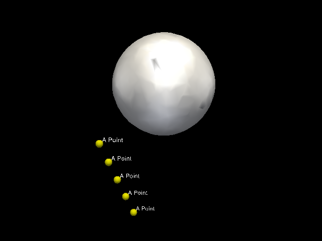
For non-image geometries the origin of the first slice and the origin
of the 3D volume does not match. The origin of the 2D planes is at the
bottom-left corner of their bottom-left pixel, but along the z axis they
must be at the middle of a 3D voxel. The origin of the 3D volume, however,
should be in the bottom-left-back corner of the bottom-left-back voxel.
That means that the origin of the first 2D slice is half voxel far from
the origin of the 3D volume along the the direction that is orthogonal to
the 2D plane.

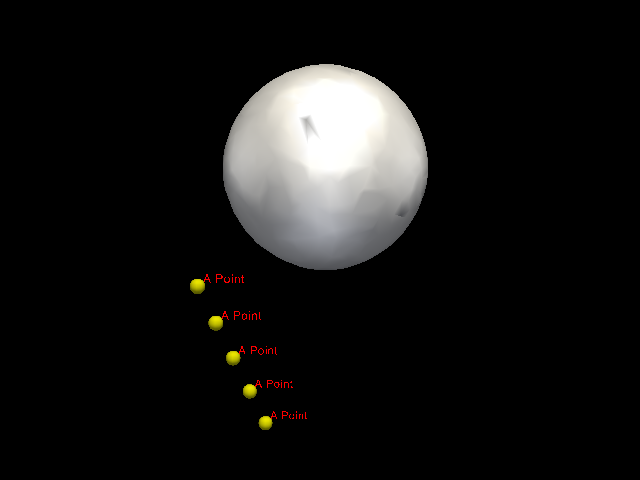
The 2D geometries must be in the middle of voxel (e.g. they are used for
the crosshair planes) and this is currently done correctly. However, the
origin of the 3D volume is now the same as the origin of the first slice
what is wrong, and causes various problems.

This fix sets the correct offset for the translation matrix of the 3D
geometry. The offset is the same as the offset of the first plane geometry
minus half spacing along the direction orthogonal to the plane.

Conflicts:
Core/Code/DataManagement/mitkSlicedGeometry3D.cpp

Signed-off-by: Miklos Espak m.espak@ucl.ac.uk
You can merge this Pull Request by running

git pull https://github.com/NifTK/MITK bug-17618-SlicedGeometry3D-with-non-image-geometry

Or view, comment on, or merge it at:

https://github.com/MITK/MITK/pull/61

Related Objects

Event Timeline

At the end I reverted this fix in our fork because it broke the MITK Display (stdmultiwidgeteditor), and we have that as well.

With the fix the crosshair was not at voxel centre in the MITK display. However, it is not correct without the fix, either. The crosshair is at voxel centre for some images, while for others it is not.

Reverting the fix also caused that I cannot display the crosshair at voxel centre in our secondary viewer.

We had a look at this problem but didn't grasp the problem. Do you have an example for a non-image slicedgeometry?

If you use a non-image plane geometry to initialise a sliced geometry then it will be a non-image sliced geometry.

In our viewer the renderers have non image sliced geometries. As far as I see it from the MITK code, it is the same for the MITK display.

The scenario:
You open an image.

Plugins/org.mitk.gui.common/src/mitkWorkbenchUtil.cpp:
LoadFiles function calculates a bounding box (TimeGeometry) from the DataStorage and calls RenderingManager::InitializeViews.

The RenderingManager calls

nc->SetInputWorldTimeGeometry( geometry );
nc->Update();

for the SliceNavigationController of the registered renderers.

The SNC::Update() creates a new sliced geometry if the input was not already 'sliced'. In this case, the 'image geometry' property is not set, and the default value is false.

The SNC sends an event about the geometry change and the BaseRenderer takes the new geometry.

As a result, the renderers will have a non-image geometry.

This is all fine. Take the 2D renderers of an StdMultiWidget and print the origin of their WorldTimeGeometry and the origin of the PlaneGeometry of its first slice. And whether they are image geometries or not.

I expect that none of them will be image geometries, and the origin of the first plane geometry will be equal to the origin of the renderer 3D geometry, although it should not.

If you print the centre of the 3D (sliced) geometry of the three 2D renderers, they will not match either (there will be a half voxel difference) although they should.

We investigated into this issue and came to following conclusion:

We think the problem is not related to the 3D-Geometry creation but is a problem of how the slices are created.

If a SlicedGeometry is not an image-geometry, its origin should not be shifted, this includes the z-axis. If its an image-geometry, all origin coordinates should be shifted by half a voxel size. For example, the origin of a PlanarFigure should not be shifted.

We think that the main problem is in the creation of the PlaneGeometries inside the SliceNavigator

We guess that the problem is caused by the method PlaneGeometry::InitializeStandardPlane(...) This method creates a shifted standard plane. See also bug-15013

For the previous comment:

This is certainly true, but in our case we create the plane geometries and the sliced geometries from our viewer, and use mitk::SliceNavigationController::Update(SliceNavigationController::Original, ...) to initialise the SNCs, so that they do *not* construct a new sliced geometry.

As all my understanding of the documentation (see geometry concepts), for non-image geometries the origin of the first plane should be different than the origin of the 3D geometry. The plane must 'cut through' the slice so that the cross hair planes are rendered correctly, and therefore its z coordinate must be at half voxel. The origin of the "compound" geometry, however should be at a corner or the volume.

Therefore, the SlicedGeometry3D::InitializeEvenlySpaced function is certainly wrong as it is now.

Michael, what's the status? Maybe reassign to Esther/Christoph?

I updated my fix to work on the last MITK release.

https://github.com/NifTK/MITK/commit/93e570ba9cc0bcf76912321fbfa9e31871700b0b

The fix does not work for oblique images, but they are not really well supported by MITK, anyway.

Esther, something for today? :)

I made some investigation in the meantime. The patch brakes a few unit tests. I have a fix for some of the failing tests. I will update pull request.

Would it be possible to resolve this for 2016.11.0? This is high priority for me and I am happy to send more patches.

First of all, do we all agree that this ticket is valid? If not, the documentation should be corrected. Now the corner point of a non-image sliced geometry is the corner of its first slice, not the corner of the volume.

espak renamed this task from SliceGeometry3D initialisation fix for non-image geometries to SlicedGeometry3D initialisation fix for non-image geometries.Sep 19 2016, 4:15 PM

I fixed a few unit tests, but some are still broken:

  • mitkPointSetDataInteractorTest
  • mitkSurfaceVtkMapper2D3DTest
  • mitkTextOverlay3DRendering3DTest_ball
  • mitkTextOverlay3DColorRenderingTest_ball

I sent a pull request based on the current master:

https://github.com/MITK/MITK/pull/142

I just updated the pull request with two new commits.

Any opinion?

These four unit tests still fail, everything else passes.

  • mitkPointSetDataInteractorTest
  • mitkSurfaceVtkMapper2D3DTest
  • mitkTextOverlay3DRendering3DTest_ball
  • mitkTextOverlay3DColorRenderingTest_ball

mitkPointSetDataInteractorTest fails because there is 0.5 difference in the z coordinate of a few points. (4 out of the 16.)

I attached the 'corrected' reference data so that the tests pass.

The other three tests use the 3D renderer. They probably fail for the same reason. I assume that the test data is slightly wrong because it was generated with an incorrectly initialised geometry.

See the change in mitk::DataStorage::ComputeBoundingGeometry3D.

I think, the easiest way to fix this would be to take the output image that the test generates and use it as a reference data. It would work as a regression test.

What do you think?

I found that these four tests pass if I comment out line 221 in mitkSlicedGeometry3D.cpp:

https://github.com/MITK/MITK/pull/145/commits/23fd9234294e0eb218f64d2b4c8eff77c04f0809#diff-f1c231a91d67b14977db027f2fa9ad76R221

The line was introduced by the first commit of this PR.

However, I still think that the line is necessary and I think the reference data is wrong because it was generated without the fix.

Here are the new reference data files for mitkSurfaceVtkMapper2D3DTest, mitkTextOverlay3DRendering3DTest_ball and mitkTextOverlay3DColorRenderingTest_ball, respectively:

mitkTextOverlay3DRendering3DTest_ball.png (480×640 px, 27 KB)

ballLUT3D_300x300.png (300×300 px, 23 KB)

mitkTextOverlay3DColorRenderingTest_ball.png (480×640 px, 27 KB)

Or see below the same changes as a patch that you can apply on the MITK-Data master. I created it based on MITK-Data e2d97a94. It contains all the five new files.

The pull request for MITK with this patch for MITK-Data fixes all the issues and all the unit tests pass. I believe they are safe to merge now. I consider this done from my part. Please let me know if you have any concerns.

I sent a new pull request after the code style changes in MITK.

https://github.com/MITK/MITK/pull/148

I have updated the PR with one more fix for mitk::DataStorage::ComputeBoundingBox(). The spacings were mixed up that led to incorrect upper bound values with images with anisotropic voxels.

At the same time I rebased the branch on your latest master and force pushed it.

I re-run the unit tests, all of them still pass with the patch on MITK-Data above. (What also means that the unit tests do not cover checking the upper bounds, actually.)

This bug report was based on the assumption that mitk::PlaneGeometry objects are actual 2D planes with 0 'thickness'. However, as I see now, plane geometries are created with 1 voxel thickness everywhere.

In spite of this, the mappers for mitk::PlaneGeometryData render the 'side wall' of the 1 voxel thick volume, not the 'centre plane' that crosscuts the volume in the middle, orthogonally to to the plane normal.

This causes that the centre of plane geometries (returned by GetCenter()) is in the middle of a cuboid, not a rectangle, and it is *not* on the rendered plane.

I tried to change this, making plane geometries with 0 z dimension. I gave it up at a crash in the 3D mapper for the plane geometry data because of an uninitialised bounding box.

Conclusion:

If plane geometries are 1 voxel thick, the origin of the plane geometries and sliced geometries should be at the same position for both image and non-image geometries. Hence, the original commit of the PR is invalid. However, it is still weird that the corner points of the renderer geometries is shifted compared to the reference geometries, so it would look better to me to render the 'centre plane' of the plane geometry 'volumes' and create the renderer geometries accordingly.

If plane geometries should be '0 voxel thick' then the original commit of the PR is valid, but many other things need to be fixed.

My final conclusion is to leave everything as it was and never touch the geometry of the renderer, but always use the reference geometry of the renderer's geometry for any calculation.

Note that the PR has some other fixes that are still valid, e.g. for mitk::DataStorage::ComputeBoundingBox3D.

I created separate tickets to save some commits from the PR:

Note that T20204 is also necessary, so that you can access the reference geometry of the geometry of the renderer, which has the correct origin and corner points.

After reading through all the comments here, it's still tough to understand the big picture. As far as I understand, there wasn't a proper fix at any one time that resolved the main issue without a catch, right? Then there was an awareness of how things actually work although there seems to be a bit of weirdness? Eventually three subtasks were created (and resolved) for related issues.

So, what's exactly left in the basket? Can you please summarize the remaining problem, if any, and how it should be solved? Thank you!

I still think that this issue is valid but it is not very important for me any more. I noticed the half voxel shift of renderer geometries compared to their input geometry, when I tried to initialise a renderer based on a geometry of another renderer.

But since then I found that instead of using the renderer's own geometry, I can access its 'input' or 'reference' geometry, that was used to initialise the renderer. So, even if the half voxel shift is incorrect in my opinion, I can use the original, 'good' geometry. (T20204)

So, I would put this on hold for now.

From the remaining issues the most important is T22114. I sent a PR that fixes all the issues with oblique images, permuted and flipped axes. It might be difficult to digest for the first sight, so I am happy to explain what it does and why. There are a couple of more little issues, I will write an e-mail about them.

kislinsk lowered the priority of this task from High to Normal.Nov 21 2016, 10:09 AM

Okay, thanks, I'll have a look at T22114 by the end of this week. I'm on a workshop Tu and We.

I agree, that there is something odd with the current behavior and I think T11113 is related, i.e., very small surfaces appear to be invisible because the camera points "half a voxel" above/below the world origin.

If you want to resolve the original issue (half voxel shift of renderer geometries) properly, I see two ways.

  1. If you think about plane geometries as actual 2D planes, you can use the fixes that I provided above.

Now plane geometries have a thickness of 1 voxel. This should be changed to 0. I started a branch with this change and fixed a few issues but gave up at a crash in the 3D renderer. I can check if I still have that branch and can share it with you.

  1. If you think about plane geometries as 1 voxel thick 3D geometries (as used now) then the fixes above are invalid, but the mappers should be changed to renderer the 'centre plane' of the slice, not the side.

The current naming is misleading because plane geometries describe a slice rather than a plane.

I would go for 1, but have not got a complete fix.

It sound like that T11113 definitely validates this issue in the sense that it does not just 'seem to be' wrong but can cause actual problems.

But then 2. should be implemented with or without 1.

But T20180 will need to be fixed as well because if the camera plane will be put on the side of the slice then it will matter in which way the normal points. Currently the handedness is a bit messed up and the plane normals can point out of the volume.

@hettich

Before you make any action on this ticket, (e.g. closing it without action), it would be good to have an overall discussion about the geometry related issues.

This report in its original form might be invalid, as well the original PR. But this does not mean that everything is all right, just that the issue might need to be handled in a different way. I started a new branch, but did not share it because it broke other things. I do not want you to go down the same route that will not work.

kislinsk claimed this task.
kislinsk added a project: Auto-closed.

Hi there! 🙂

This task was auto-closed according to our Task Lifecycle Management.
Please follow this link for more information and don't forget that you are encouraged to reasonable re-open tasks to revive them. 🚑

Best wishes,
The MITK devs

kislinsk removed kislinsk as the assignee of this task.May 26 2020, 12:05 PM
kislinsk removed a subscriber: kislinsk.