Page MenuHomePhabricator

Provide opacity property for first color in Lookup Table
Closed, ResolvedPublic

Assigned To
None
Authored By
clarkson
Nov 17 2011, 3:32 PM
Referenced Files
F761: alles-bunt-und-binary.png
Mar 7 2012, 6:07 PM
F760: wieder-ganz.png
Mar 7 2012, 4:29 PM
F759: z-fighting.png
Feb 1 2012, 5:49 PM
F758: halber-fix.png
Jan 31 2012, 6:58 PM
F757: MITK-ohne-LUT0-transparent.png
Jan 31 2012, 6:54 PM
F756: lut-rendering.png
Jan 31 2012, 6:52 PM
F755: opacity7.jpg
Nov 23 2011, 4:42 PM
F754: opacity0.jpg
Nov 23 2011, 4:41 PM

Description

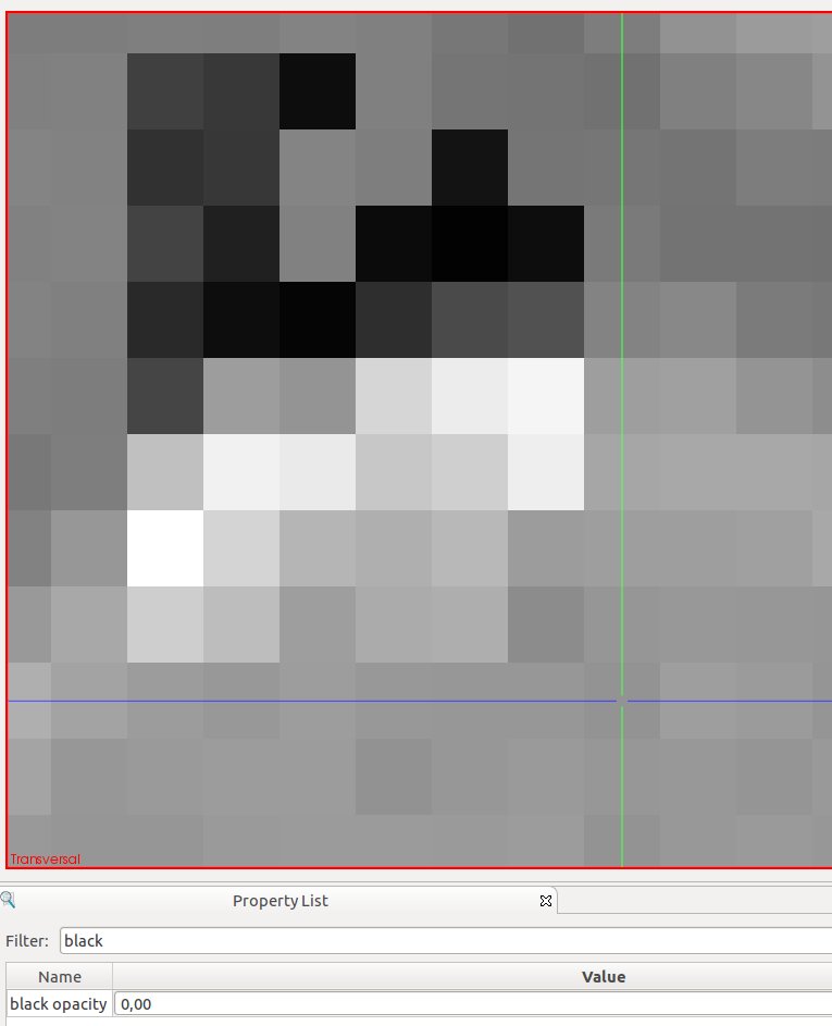
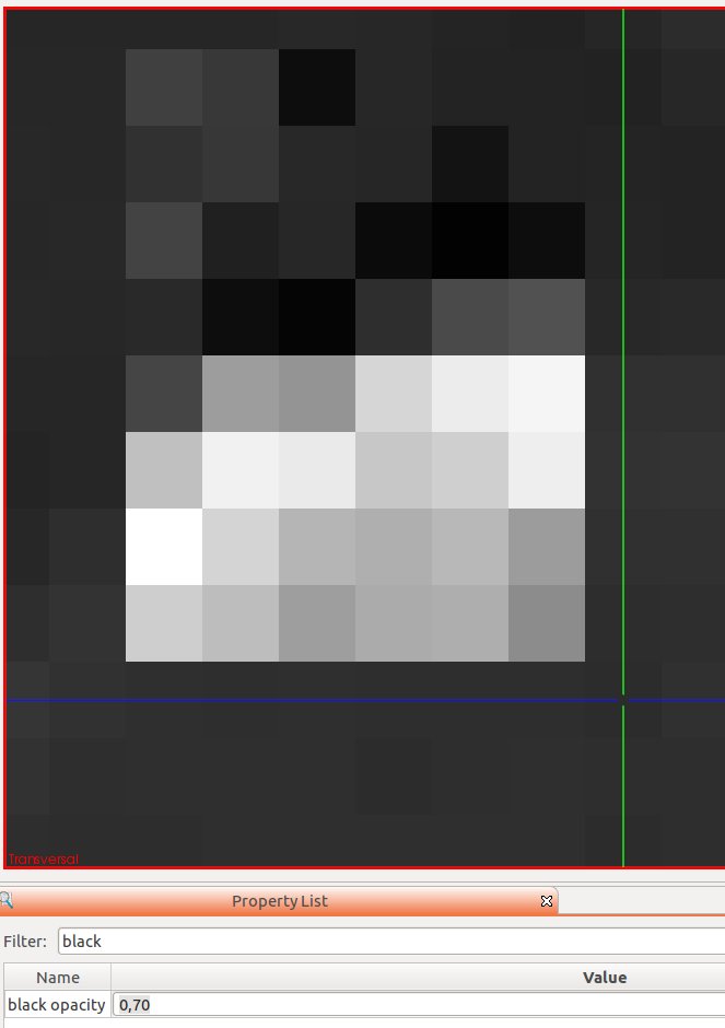
The first colour in a lookup table is hardcoded to be transparent.

https://github.com/MITK/MITK/blob/master/Core/Code/Rendering/mitkImageVtkMapper2D.cpp#L1144
https://github.com/MITK/MITK/blob/master/Core/Code/Rendering/mitkImageVtkMapper2D.cpp#L675

This is OK if the background is black. When a given data value is mapped to transparent, and the background of the rendered scene is white, you can see the background white colour through the image.

Please can we add an opacity property that defaults to zero (for minimal impact) that can be set 0-1 to control the opacity.

Event Timeline

I checked out your branch and tested it. Your code is quite simple, however, the behavior of the property is a bit strange if you load two images of different dimensions.

The background of the image with the smaller dimension will also become visible and you cannot see the second image anymore. Attached you can find two screenshots showing this behavior.

We will discuss this issue in of our upcoming meetings.

image with black opacity = 0 (current, common case)

opacity0.jpg (943×765 px, 36 KB)

image with black opacity = 0.7. Total background becomes black.

opacity7.jpg (940×663 px, 34 KB)

(In reply to comment #4)

Created attachment 1090 [details]
image with black opacity = 0.7. Total background becomes black.

Hi there, I am not sure what your screenshots are trying to illustrate. With "black opacity" = 0, the functionality should be exactly the same as the current master. It is only in the cases where the user specifies a different number such as "black opacity" = 1 that they will see a difference. and if two images are loaded, there one is a different size, then it will extend pass the other as you say, but this is intended behaviour. So the user has a choice of what to set.

So, I can't make any code change, as I don't know what you are suggesting I change. As I see it, the code works as expected.

Thanks

Matt

Your code works as expected but we are looking for a smarter solution. It would be great if we could distinguish between background and image value pixel. The background would be always transparent and the image pixel value always visible. In that case, this property would most likely be unnecessary. However, we don't know if this is feasible. We will arrange an additional internal meeting for this issue.

(In reply to comment #7)

Hi there,

ok, we agree that the code works "as expected".... but yes it is a bit basic.

In addition, the code needs to be as fast as possible, so nothing too clever, as it affects all the rendering.
We could have different behaviour for binary masks, as here, I think in EVERY case you would want the bottom value in the colour map to have opacity=0.

Apart from that, I would not suggest making it too complicated.

Markus and I discussed this:
In general, we think it is not useful to map the lowest value of any image (except binary) to transparent. However, the background value of any image should almost always be transparent and it is very complicated to ensure that the background value does not appear inside the image.

On the one hand, the vtkImageReslice is able to set a background color. On the other hand, we do not set this value specific yet for the data type. If we have an unsigned char image, for instance, the background value should be set to 0 and all image values should be mapped to 1 - 255.

(In reply to comment #9)

Hi there, Im not sure I understand what you are saying:

Markus and I discussed this:
In general, we think it is not useful to map the lowest value of any image
(except binary) to transparent.

The current functionality, in current MITK is that the lowest value in the lookup
table is set to opacity=0. So, are you saying that you don't think this is right
for any image, or just for binary images?

However, the background value of any image
should almost always be transparent and it is very complicated to ensure that
the background value does not appear inside the image.

True, I agree. In addition, we must remember that we are only discussing the
first value in a lookup table, not the lowest value in the image. These are different.

On the one hand, the vtkImageReslice is able to set a background color. On the
other hand, we do not set this value specific yet for the data type. If we have
an unsigned char image, for instance, the background value should be set to 0
and all image values should be mapped to 1 - 255.

The background colour is normally used for when you resample outside the image
volume, as you have no other data. This is different to the lookup table issue.

So, I'm not sure where we are with this bug. The code I provided should have minimal
impact, and appear to be no different for anyone currently using MITK, as the
current functionality is to map the lowest value in the lookup table to have an
opacity of zero. So, I don't mean to be rude when I ask whether you are intending
to merge my code, or whether you think it conflicts in any way with MITK?

Thanks

Matt

Hi Matt,

as I mentioned before, we are discussing this bug internally. We planned another meeting sometime in december to decide how to solve this issue. We want to check what possibilities we have and we want to ask the authors about the reasons for the current behavior.

I totally agree with you that your solution does have minimal impact etc., however, it introduces another property (we want to have as less properties as possible). The property behavior could look strange for people from the medical area and only programmers with rendering knowledge will understand it immediately. So we want double-check if there is some "better" solution.

Since you are familiar with the rendering techniques, do you think there is any possibility to realize a more generic solution even if this would take more effort? Is there a decent way to distinguish between fore- and background values?

I think there is still a pretty high chance that we just take your solution, because it is straight forward and already implemented, but I can't guarantee anything. I am not the one to decide this. I guess until then you have to be patient and use your own modification to apply your property. Im sorry!

(In reply to comment #11)

Hi Matt,

as I mentioned before, ... snip ... is some "better" solution.

OK, I understand. It's not a problem at all.

Since you are familiar with the rendering techniques, do you think there is any
possibility to realize a more generic solution even if this would take more
effort? Is there a decent way to distinguish between fore- and background
values?

I don't think so. An additional problem is that different modalities will have different background values.
For example, an image such as CT often has a constant value round the edge as the scanner reconstructs a cylindrical region of interest, and packs the rest of the voxel grid with a constant value to make a cuboid image. For example, I believe air is -2000, but background is -3000 or so. MR images don't really have this, and so the background is noisy rather than a constant value. Furthermore, after some processing, people often pad background inconsistently so you can have post processed data with no guarantee of what the background is. Additionally, if you have a binary mask for example of the grey matter, where grey matter = 255 and all background is 0 then this is well suited to having the opacity as zero as MITK already has it. However, if a person is using probability masks where the grey matter has values between 0 and 1, then as soon as a probability value is low enough to get mapped to the lowest value in the lookup table, it will disappear, possibly leading to misleading edges. In short, I think this is very difficult to do consistently, and is very modality and application specific.

I think there is still a pretty high chance that we just take your solution,
because it is straight forward and already implemented, but I can't guarantee
anything. I am not the one to decide this. I guess until then you have to be
patient and use your own modification to apply your property. Im sorry!

Ok, I can wait. I can either use my github version, or just set the background of my rendering window
to black to hide the effect!

Thanks

Matt

Hi there people.

Any update on this?

THanks

Matt

We will have a meeting about this on the 24th.

Update on this issue:

On Friday I had a discussion with Markus Fangerau and Thomas Kilgus. We agreed on

  • how 2D rendering currently works
  • what problems arise with lookup tables
  • how this could be fixed.

Today I started solving the issue together with Markus Engel. So far we

  • understood most of the 2D rendering code (notes for further documentation added)
  • found how 2D rendering can be easily corrected
  • faced the fact that the 2D texture is reused for rendering of render window planes in 3D and that this 3D rendering expects a given extent of the textures. This is currently not working nicely.

Tomorrow all of us will meet at DKFZ and try to complete the solution. Hopefully
this will prove as simple as it looks now.

I'll attach a few screenshots and a sketch of our solution to this bug shortly.
I intend to enhance the documentation of the 2D mapper once we have the complete
solution. It should contain a description of the current problem and its solution
so that maintainers can understand the mapper structure..

This sketch summarizes 2D rendering

  • in general
  • as the overlapping of multiple images is solved in current master
  • how we propose to fix the problem

(The skewed rectangles are supposed to show 2D planes layerd in 3D space...)

lut-rendering.png (479×843 px, 77 KB)

This shows the rendering output if we remove the current workaround (which sets the lowest lookup table value to transparent). The overlay image (colored) is actually limited to about half the extent of the CT. However, rendering uses the complete space and fills areas outside the image with the lowest LUT value (in this case blue)

MITK-ohne-LUT0-transparent.png (726×495 px, 117 KB)

This screenshot shows the rendering when a simple initial fix is applied.

Problem here: the 3D rendering stretches the textures onto the full planes (which comprise the union of both images). The 2D solutions seems to work fine.

!!!!!!!!!!!!!!!!!!!
Changes to get this rendering are in branch "personal/maleike/rendering-clipping-2d" (this MUST not be merged into master, it contains much noise)

halber-fix.png (883×1 px, 186 KB)

Summary of today's bugfixing session:

  • we enhanced yesterday's solution to fix the 3D rendering
  • the current fix is based on personal/schroedt/integrationbranch_bug-9318, which refactors the 2D slice extraction (used both in image mapping and segmentation) into a class of its own

Solved:

  • rendering now paints the textures
    • in 2D and 3D
    • at the right positions
    • with the right scale
    • background is not contained in the textures

New problem:

In 3D rendering, we now paint multiple textures on different planes, each with its own origin/extent. This leads to "z fighting", i.e. a kind of flickering effect. After some research we did not find a simple solution for this issue...

New approaches for a solution:

In any case, forget about really clipping the textures to a smaller extent

One of
a) transform the texture images into RGBA images (must consider L/W

transformation). Then paint the pixels outside the image bounds
with a transparent color

b) in Geometry2DDataVtkMapper3D, provide each DatasetMapper with individual

clipping planes, which represent the 2D image extent.

c) implement a custom shader for clipping the textures

OR find a VTK based solution to this "z fighting"..

The currently preferred solution is b), because we don't have to transform the image pixels ourselves and leave this to VTK..
We'll individually try to work on a solution and meet again next Wednesday.

Attached image shows how 3D rendering looks with "z fighting"

z-fighting.png (419×478 px, 114 KB)

The current workaround is available on branch personal/schroedt/lut-clipping-issue-2d-3d

I just tried to introduce clipping planes into the scene: branch personal/maleike/lut-clipping-issue-2d-3d-clipping-planes

The result was that the clipped part of a plane was still shining through somehow, looks similar to z fighting. No clear idea yet why this is happening..

We now implemented the "use RGBA texture and set out-of-image pixels to alpha=0" approach. It seems to work correctly on simple grayvalue images (see attached image).

TODOs

  • integrate handling of RGBA images ("opac level/window") into new vtkMitkLevelWindowFilter, remove special cases for RGBA images
  • test with more special images
    • RGB
    • Binary
    • Strangely rotated geometries
    • Test behavior with abstract geometries (curved planes). in this case our clipping logic does NOT calculate a result
  • clean up code, document
  • communicate new behavior: LUT[0] will NOT be mapped to transparent anymore
  • implement test case for automated rendering tests

wieder-ganz.png (397×642 px, 82 KB)

Now we tested RGB, RGBA, and binary images. All seems to work.

Klaus, we are not sure that we covered all cases of your diffusion use cases. Could you please check the behavior with your images, esp. with the "opac level window" property?

Next step for me would be to clean up the code, remove obsolete parts, and document the old and structures.

alles-bunt-und-binary.png (778×1 px, 285 KB)

(In reply to comment #25)

Klaus, we are not sure that we covered all cases of your diffusion use cases.
Could you please check the behavior with your images, esp. with the "opac level
window" property?

Branch name is 'personal/maleike/lut-rendering-alles-einfacher'

I absolutely recommend to perform the rendering test protocol, before pushing into the master. It can be found here:
http://www.mitk.org/wiki/internal/RenderingTest

Christoph and Basi performed some testing with the following outcome:

-Property "use color" cannot be deactivated (This bug was present some time in the master and fixed. Maybe your branch is from that time. But double check this after the merge.)

-The order of the 3D images is incorrect regarding translucent and opaque images. Translucent images are rendered after opaque images and thus can overwrite them. (Just load two images and make the lower in the data storage transparent.) Could be related to T7617.

-Z-Buffer is incorrect when volume-rendering is activated. (Just load an image, enable volume-rendering and play with the 3D render window.)

-The level window is always applied to the first data node of the data storage, no matter which node is selected. (Load two images, select the second and play with the level window.)

-2D rendering is extremely slow even in release (in Windows) compared to the current master. Could also be fixed in the current master, but we have to double check this. Could also be related to the new lut stuff.

-The brain.mhd dataset shows wired behavior regarding reinit.

-(Transparent) Segmentations overwrite the image in the 3D renderwindow. (Load an image and add a segmentation ("outline binary" property off. The segmentation will be visible, but not the image underneath.)

We also found some bugs which are definitely fixed in the current master (for instance the 3D render window uses a different vtkInteractor). We should make an integration branch for this bug and perform the testing again to figure out what is related to the work in this bug branch and what is already fixed in the current master.

Basti just verified that these bugs are only present on your branch:

-Property "use color" cannot be deactivated (This bug was present some time in the master and fixed. Maybe your branch is from that time. But double check this after the merge.)

-The order of the 3D images is incorrect regarding translucent and opaque images. Translucent images are rendered after opaque images and thus can overwrite them. (Just load two images and make the lower in the data storage transparent.) Could be related to T7617.

-(Transparent) Segmentations overwrite the image in the 3D renderwindow. (Load an image and add a segmentation ("outline binary" property off. The segmentation will be visible, but not the image underneath.) Could be the same issue like the one above.

-Z-Buffer is incorrect when volume-rendering is activated. (Just load an image, enable volume-rendering and play with the 3D render window.)

-2D rendering is extremely slow even in release (in Windows) compared to the current master. Could also be fixed in the current master, but we have to double check this. Could also be related to the new lut stuff.

Markus F., you said you and Anja had worked on this issue. Could you please tell about the progress? Is this related to / solving T11948 / T11106?

(In reply to comment #31)

Markus F., you said you and Anja had worked on this issue. Could you please
tell about the progress? Is this related to / solving T11948 / T11106?

Hi Daniel,

This T10174 is not related to either 11948 or 11106. However, I'm still interested in the outcome of 10174. Originally, I put in a really simple property so make the first colour in the lookup table (normally black) to have its own opacity setting. I called this "black opacity". The idea was to then look for a "smarter" solution, but I don't think it is finished. I believe this smarter solution also turned out to be a lot of work and was never merged.

Matt

(In reply to comment #32)>

This T10174 is not related to either 11948 or 11106.

Hi Matt,

I'm still curious for Markus' report, but I can also summarize what I know: Markus and I developed a solution for this problem here, which worked but contained quite some redundancy and dirty code. Lately Markus told me he was cleaning up everything because he needs the results. On a different issue (11948/11106) the 3D texture rendering seems to be the cause of rendering offset errors and a colleague was told these issues would be solved with some work of Markus and I suspected this could be this issue. We'll see...

Extremely high important, because we are waiting for this almost a year now and have investigated lots of recourses for implementation AND testing! What is the status Markus/Daniel? Didn't you want to put this into the 2012-06 release?

Just confirmed with Markus: this will be fixed together T8165, which already has a solution pushed which is waiting for integration.

Updated target milestone. Adapted severity.

As far as I know this bug is fixed with the latest changes of Markus and Sandy. See T8164 for details.